SoundObject によるステレオススピーカーサウンドのヘッドホンモニタリング
Note: SpeakerObjects のリリースにより,本記事は不要となりました.
ステレオススピーカーからの再生を想定したサウンドを,ヘッドホンでモニターすると,定位感が損なわれる.同様に,ヘッドホンモニタリングによってミキシングされたサウンドを,ステレオススピーカーから再生すると,サウンドのバランスが崩れる.この場合は,モニタリングの際にリスニングルームの音響特性の補正が必要であり,SoundObject はそれをサポートする事ができる.本ノートは SoundObject によるステレオススピーカーサウンドのヘッドホンモニタリング方法について述べる.
トラックの構造
ルーチング
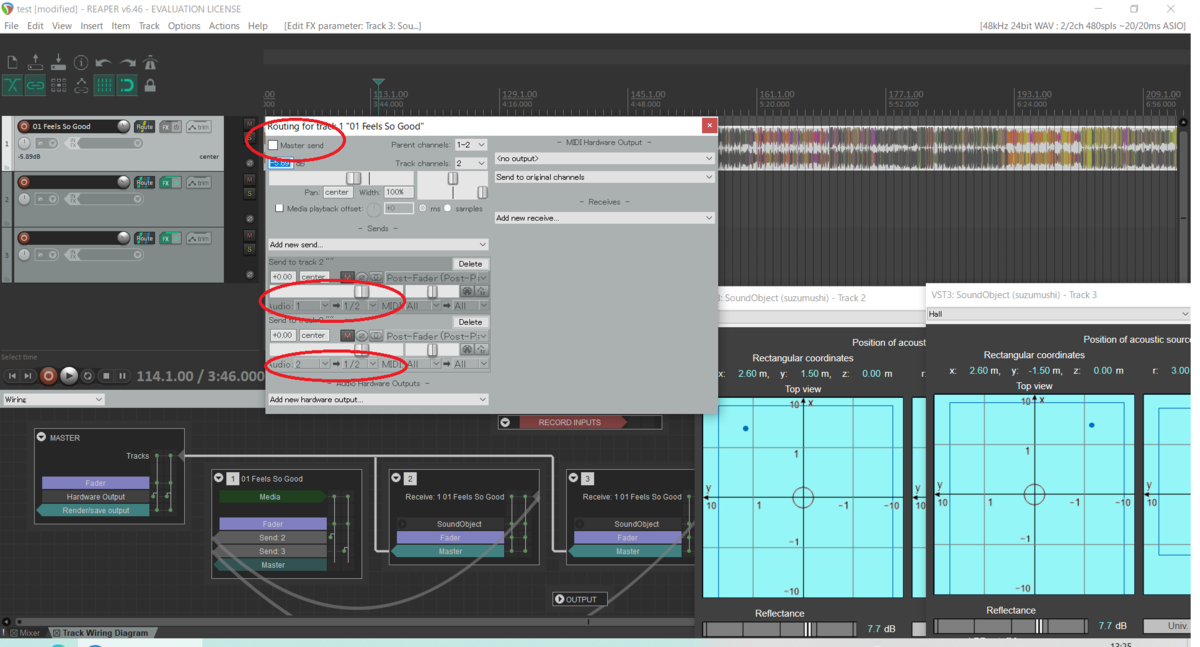
以下,Reaper の設定を例として示す.
- ステレオサウンドのトラックの master send を停止する.
- ステレオサウンドの左チャネルを,左チャネルのトラックに送る.
- ステレオサウンドの右チャネルを,右チャネルのトラックに送る.
- 左チャネル,右チャネルのトラックを master send とする (default 設定).即ち,SoundObject の出力をミックスしてモニタリングする.
SoundObject の設定
- 残響室の寸法 (Dimensions of reverberation room) リスニングルームのサイズ,球の中心 (Center of sphere) をリスニングポジションとする.球の中心はリスニングルームに対して非対称な位置とする事を強くお勧めする.
- 音源の位置 (Position of acoustic source) を左右のスピーカーの位置に設定する.
- 出力 (Output) として,合成波 (Combined waves) とヘッドホンによる 3D サウンド (Binaural) を選択する.
- Reflectance (反射率) と LPF cutoff frequency (LPF のカットオフ周波数) を好みに合わせて設定する.
参 考
Pinna Scattering Effect Filter
This document describes details of pinna scattering effect filter. It outputs convolution of an input and impulse response that represents scattering by the pinna, then enables senses of front-back and upward-downward directions. However, similar to conventional binaural sound processors, it rarely creates a sense of front distance. Therefore, SoundObject makes possible senses of front-back and upward-downward distances by reflected waves in a reverberation room. Finally, this document describes the evaluation of pinna scattering effect filter then clarifies that it enables senses of front-back and upward-downward directions and reflected waves make possible clearer senses of distances.
1. Scattering by a pinna
It is well-known that senses of front-back and upward-downward directions to an acoustic source mainly arise from scattering effects by pinnae (earlobes). Since the average length of a pinna is roughly 60mm, the frequency whose wave length is equal to a pinna length is approximately 5,800Hz, where acoustic speed is 345m/s. Therefore, scattering by a pinna becomes prominent in audio frequency over a few thousand Hz, thus this frequency band is essential to enable senses of front-back and upward-downward directions.
SoundObjcet enables senses of leftward and rightward distance by the sphere scattering effect filter and direction by interaural time and level differences. However, they don't make possible senses of front-back and upward-downward directions. Furthermore, over 3,000Hz, there is no significant difference in the directional characteristics of the sphere scattering effect filter. Therefore, SoundObject assumes that scattering by a head consists of scattering by a rigid sphere and pinnae, thus implements sphere and pinna scattering effect filters independently.
2. Pinna scattering effect filter
Pinna scattering effect filter outputs convolution of an input and impulse response that represents scattering by the pinna. Pinna-related impulse responses of SoundObject are derived from open head-related impulse response (HRIR) databases. The following coordinates system is based on the SOFA specification.
HRIR whose azimuth angles φ = 0 and 180 deg. could be regarded as not including the response to y axial component of the incident wave. In the other azimuth angle cases, HRIR contains the response to y axial component, while it does not impact on senses of front-back and upward-downward directions. Therefore, pinna-related impulse responses of SoundObject are extracted from HRIR databases whose azimuth angles φ = 0 and 180 deg. Furthermore, they are applied to the other azimuth angles.
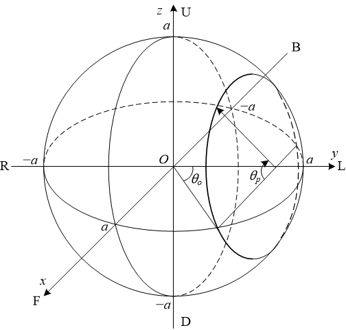
To apply the impulse responses whose azimuth angles φ = 0 and 180 deg. to the other angle cases, as shown in Fig. 1, pinna scattering effect filter defines θp (−180, 180] deg. as the elevation angle to the acoustic source measured counter clockwise from the x-axis on the plane parallel to the x-z plane and passing through (0, a cos θo, 0).
3. Pinna-related impulse response
Pinna-related impulse responses of SoundObject are extracted from HRIRs of KU 100 and KEMAR dummy heads in SADIE II Database [1] and KEMAR dummy head in high-resolution HRTF data set [2]. Impulse responses, whose azimuth angles φ = 0 and 180 deg. and the sampling frequency is 48KHz, derived from these databases are shown in Fig. 2, where horizontal and vertical axes show time and θp respectively, and green, and red gradations indicate higher and lower values respectively.

Since measurement results of HRIR highly depend on measuring object, method, and instrument, the above responses indicate diverse results. However, distinctive impulse responses concentrated approximately consecutive 24 samples are commonly observed. In 48KHz sampling, the time for 24 samples is 0.5ms. And during this time, a sound wave is propagated 173mm, where acoustic speed is 345m/s. Since the average length of a pinna is roughly 60mm, the above sample number seems sufficient for impulse response representing scattering by a pinna.
Thus, in a 48KHz sampling case, a pinna-related impulse response of SoundObject is consecutive 24 samples extracted from an HRIR. Fig. 3 shows a comparison of frequency responses calculated from 256 and 24 samples in the HRIR data set [2], where elevation angle θp = 0. The result shows that 24 samples could sufficiently represent the frequency response.

4. Evaluation
Similar to conventional convolution-based binaural sound processors, pinna scattering effect filter rarely creates a sense of front distance. Therefore, SoundObject makes possible senses of front-back and upward-downward distances by reflected waves in a reverberation room.
SoundObject could select the output from direct wave and combined waves that consist of direct and reflected waves. Therefore, the pinna scattering effect filter could be evaluated with comparisons of these outputs. As shown in the following video, the former output indicates senses of front-back and upward-downward directions for all azimuth angles. Furthermore, the latter demonstrates a clearer sense of distance.
References
[1] SADIE project, "SADIE II Database," University of York, EPSRC, June 2018.
[2] H. Braren and J. Fels, "A High-Resolution Head-Related Transfer Function Data Set and 3D-Scan of KEMAR," RWTH Aachen University, December 2020.
Sphere Scattering Effect Filter
This document describes details of sphere scattering effect filter. It inputs an incident wave to a rigid sphere then outputs the incident and scattered waves by the sphere. SoundObject enables a sense of leftward and rightward distance with it. Since the exact solution of the scattering by a rigid sphere is complicated, an approximate solution based on the dipole source is proposed. Next, the frequency and directional characteristics of the scattering effect by a sphere based on the proposed approximation are explained. Finally, this document describes the design and evaluation of the digital filter implementing the scattering effect by a sphere then clarifies that it enables a clearer sense of distance compared with the effects based on interaural time difference (ITD) and interaural level difference (ILD).
1. Scattering by a rigid sphere
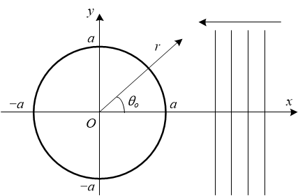
As shown in Fig. 1, we assume a plane wave propagating to the negative direction of the x-axis as against a rigid sphere whose center is located at the origin and radius is a. Let G (jω) be a frequency transfer function representing a ratio of sound pressure observed in the surface area of the sphere to that of the plane wave. We find G (jω) from the acoustic fields of the plane wave and the scattering waves from the sphere observed at coordinate (r, θ0). In this case, the virtual sound source position of the scattering is located at the origin. In this document, j, t, c, ω, k, and ρ denote the imaginary unit, time, acoustic speed, angular frequency of the wave, wavenumber (k = ω/c), and medium density respectively.
Note: The above coordinate system is different from that of SoundObject.
1.1 Exact solution
The exact solution for the above problem is well known [1]. The acoustic field of plane wave pi is given below, where Pn denotes Legendre polynomials and jn denotes spherical Bessel functions.
And the acoustic field of scattering waves pr is given below, where hn(2) denotes spherical Hankel functions.
Therefore, the frequency transfer function G (jω) representing a ratio of sound pressure observed in the surface area of the sphere to that of the plane wave is given below.
1.2 Known approximate solutions
Since the above exact solution is computable but highly complicated, approximate solutions are proposed. [1] and [2] show approximations of scattered waves for ka ≪ 1. However, in head approximation by sphere, the frequency that gives ka = 1 is approximately 760Hz. Thus, these are unpractical for this application. Furthermore, [2] describes an approximation of scattered waves by the dipole source for kr ≪ 1, while it is also inapplicable. Therefore, this document proposes a further approximation of scattered waves by the dipole source.
1.3 Proposed approximate solution
Let Φi be the velocity potential of a plane wave observed at coordinate (r, θ0). It is given below, where A is an undetermined coefficient.
We approximate the scattered waves by the dipole source located at the origin. Let Φr be the velocity potential of scattered waves observed at coordinate (r, θ0). It is given by the following equation, where B is also an undetermined coefficient.
Therefore, the velocity potential Φ in the neighborhood of the sphere is given below.
To obtain the particle velocity, we find the normal derivative of the above equation.
The particle velocity is 0 at r = a.
Thus, the velocity potential Φ in the neighborhood of the sphere is given below.
Finally, the velocity potential in the surface area of the sphere is given below.
2. Transfer function of scattering effect by sphere
Based on the above discussions, the frequency transfer function G (jω) representing a ratio of sound pressure observed in the surface area of the sphere to that of the plane wave is given below.
The transfer function G (s) corresponding to the above frequency transfer function G (jω) is given below, where ωc = c /a.
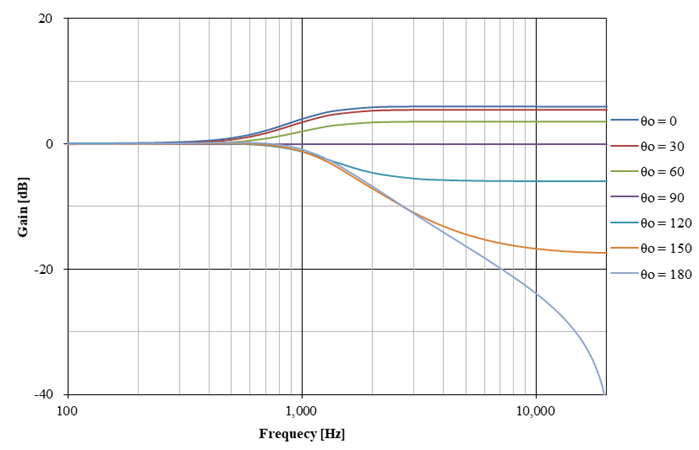
An example of frequency characteristics of G (jω) is shown below, where c = 343.7 m/s and a = 71.5 mm.

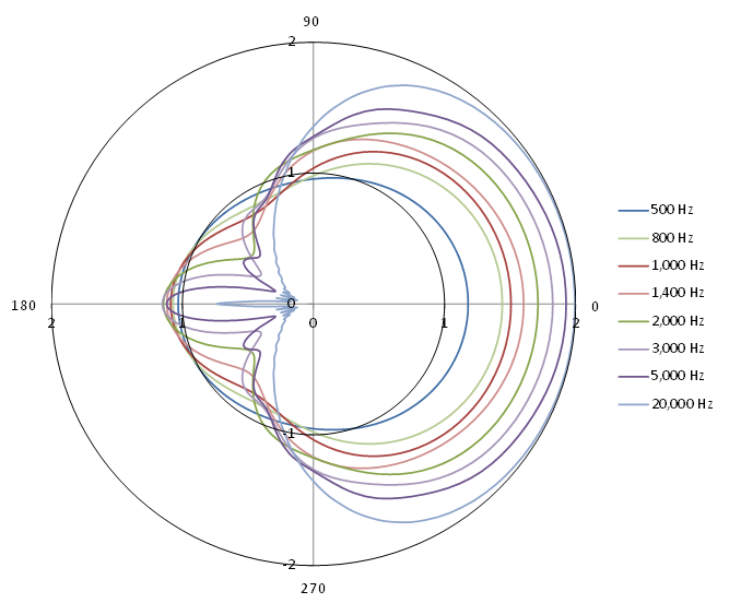
And an example of directional characteristics of G (jω) is also shown below, where the radius direction and angle from the x-axis show gain (ratio) and θo respectively. The frequency whose wave length is equal to the diameter of the sphere is approximately 2,400Hz. The figure illustrates that the incident wave less than 2,000Hz is significantly propagated to the behind of the sphere. However, over 2,000Hz, differences in the front directional gain are rarely observed. Furthermore, over 3,000Hz, there is no significant difference in the directional characteristics.

For reference, an example of directional characteristics of the frequency transfer function based on the exact solution numerically calculated from equation (3) is shown below. Although slight differences are observed in detail, directional characteristics tendencies based on the exact and approximate solutions are the same. Since head is not a strictly rigid sphere, sufficient effects are expected by the proposed approximate solution.
Note: A numerical calculation program of the exact solution is available on the following link.
3. Sphere scattering effect filter
With bilinear transformation, we find an infinite impulse response (IIR) filter that implements a system transfer function H (z) equivalent to the transfer function G (s) denoted by equation (12). Bilinear transform-based design method for IIR filters is well-known, thus leaving out a detailed explanation. If needed, refer to the following document. (In Japanese).
The correspondence relationship between angular frequencies of the transfer function G (s) and system transfer function H (z) is warped by bilinear transformation. Therefore, compensated angular frequency ωa corresponding to ωc is shown below, where T denotes sampling interval.
Thus, the system transfer function H (z) is given below.
The above could be essentially implemented as a second-order IIR filter (biquad filter). An example of frequency characteristics of the above digital filter is shown below, where T = 1 /44,100 s.
4. Evaluation
SoundObject could select the output from scattered waves by the sphere and incident wave with ITD and ILD. Therefore, the sphere scattering effect filter could be evaluated with comparisons of these outputs. As shown in the following video, the latter output sounds like the acoustic source locates close to the ear regardless of the distance. On the other hand, the former demonstrates a clearer sense of distance enabled by the sphere scattering effect filter.
References
[1] P. M. Morse, "Vibration and Sound, Second Ed.," International series in pure and applied physics, McGRAW-HILL, 1948.
[2] T. Ito, "Principles of Acoustic Engineering," Corona Publishing, 1955 (In Japanese). Acoustic Lab. - Waseda Univ.
SoundObject
1. Overview of SoundObject
SoundObject creates a binaural sound with the senses of three-dimensional sound localization from a monaural acoustic source and its positional information. It supports headphones-based as well as stereo speakers-based 3D spatial sound. Furthermore, it could also support headphones monitoring of stereo speaker sound.
Conventional three-dimensional binaural sound processors implement sound localization with the convolution of an acoustic source and head-related impulse response (HRIR) that represents scattering by the head. Since the convolution consumes a large amount of computational resource, SoundObject assumes that scattering by a head consists of scattering by a rigid sphere and pinnae (earlobes), then enables sound localization with simplified sphere and pinna scattering effect filters.
And in many cases, conventional convolution-based binaural sound rarely creates a sense of front distance, while SoundObject enables it by reflected waves in a reverberation room.
Furthermore, Doppler effect inevitably results from a moving acoustic source. Generally, sine waves whose frequency difference is 0.3% are distinguishable as different sounds. This fact implies that the recognizable Doppler effect results from an acoustic source whose speed exceeds approximately 1m/s, where acoustic speed is 345m/s. Since 1m/s is never high speed, SoundObject constantly adds Doppler effect when an acoustic source is moving.
SoundObject is provided as a VST 3 plug-in for digital audio workstations (DAW) and supports 44.1KHz, 48KHz, and 96KHz sampling rates. OS environments are 64bit Windows 10 and macOS 10.14.
SoundObject binary distribution is licensed under Creative Commons Attribution 4.0 (CC BY 4.0) at no charge.
SoundObject source code distribution is licensed under Creative Commons Attribution-NonCommercial-ShareAlike 4.0 (CC BY-NC-SA 4.0) at no charge.
2. Block diagram of SoundObject
SoundObject enables senses of three-dimensional directions, distances, and speed by the following:
- A sense of leftward and rightward direction by interaural time difference (ITD) and interaural level difference (ILD).
- A sense of leftward and rightward distance by sphere scattering effect filter.
- Senses of front-back and upward-downward directions by pinna scattering effect filter.
- Senses of front-back and upward-downward distances by reflected waves.
- A sense of speed by Doppler effect.
A single channel block diagram of SoundObject is shown in Fig. 1.

As shown in the figure, a single channel of SoundObject inputs a monaural acoustic source, then creates a direct wave, reflected waves from 6 directions, and combined waves of them. And it finally outputs as headphones-based (binaural) or speakers-based (transaural) 3D sound.
Delay line and resampler
SoundObject implements ITD and ILD with a delay line and Doppler effect with a resampler. The latter is supported by polyphase decomposition-based up and down sampling. For example, in the case of a 48KHz sampling input signal, it is once converted into a 43.2MHz−52.8MHz sampling signal then outputted as a 48KHz sampling signal. Polyphase decomposition-based up and down sampling is a well-known technology, thus leaving out a detailed explanation.
Sphere scattering effect filter
Sphere scattering effect filter inputs an incident wave to a rigid sphere then outputs the incident and scattered waves by the sphere. Details are described in the following document.
Pinna scattering effect filter
Pinna scattering effect filter outputs convolution of an input and impulse response that represents scattering by the pinna. Pinna-related impulse responses of SoundObject are derived from open head-related transfer function (HRTF) databases. Details are described in the following document.
Coordinate converter
Coordinate converter calculates delay, decay, and angles such as θo and θp of direct and reflected waves from a position of the acoustic source, dimensions of the reverberation room, and a position of the sphere in real-time.
To monitor the effects of digital signal processing units described above, SoundObject could select the output from combined waves as well as direct wave, reflected waves, scattered waves by the sphere, and incident wave with ITD, ILD, and Doppler. And reflected waves pass through a low pass filter. It could change the feeling of reflected waves.
3. Operation of SoundObject
Coordinate system
Coordinate system of SoundObject based on the spatially oriented format for acoustics (SOFA) defined by AES69-2020 [1] specification is shown in Fig. 2.

As shown in the figure, in SoundObject, the center of the sphere is located at the origin. And x, y, and z-axis directions are the front, leftward, and upward directions respectively. In the polar coordinates system, radius r is the distance from the origin to the acoustic source, elevation angle θ [−90, 90] deg. is measured from the x-y plane, and azimuth angle φ [0, 360) deg. is measured counterclockwise from the x-axis. The depth, width, and height of the reverberation room are the distances of x, y, and z-axis directions respectively. And distances to the center of the sphere are measured from the point shown in the figure.
Note: The definition of elevation angle in AES69-2020 is different from the typical definition.
User interface
User interface of SoundObject is shown in Fig. 3.

The position of the acoustic source colud be set from any of the rectangular coordinates, the polar coordinates, the x-y pad illustrating the top view, and the y-z pad also illustrating the rear view. It is constrained by the inside of the reverberation room shown by the rectangles.
The distance attenuation slider indicates the distance decay of direct and reflected waves. −6 dB means decreasing by half when the distance to the acoustic source is doubled (i.e., point sound source: compatible with SoundObject ver. 2 and earlier) and 0 dB means no attenuation (i.e., plane sound source).
The reflectance slider indicates the reflectance of the reverberation room. Typically, it is set to less than 0 dB, however, in a large reverberation room, it may be set to over 0 dB because the level of reflected waves decreases due to distance attenuation.
The LPF cutoff frequency slider denotes the cutoff frequency of the LPF for reflected waves. However, in the case of ∞ KHz, the LPF function is invalidated.
The HRIR option menu selects the HRIR database used by the pinna scattering effect filter. And the output option menu selects monitoring outputs described in section 2. It also selects headphones-based (binaural) or speakers-based (transaural) 3D sound. Furthermore, as shown in Fig. 4, azimuth to the left speaker is measured from the x-axis.

Descriptions for dimensions of the reverberation room and center of the sphere are explained in the coordinate system. In addition to these, settings for acoustic speed and radius of the sphere are updated during the DAW is not playing, that is, not updated in real-time.
Headphones monitoring of stereo speaker sound
Refer to the following.
References
[1] Audio Engineering Society, "AES standard for file exchange - Spatial acoustic data file format," AES69-2020, December 2020.
VST is a registered trademark of Steinberg Media Technologies GmbH.

耳介散乱効果フィルタ
本ドキュメントは耳介散乱効果フィルタの詳細を述べる.耳介散乱効果フィルタは,入力と耳介による散乱を表すインパルス応答を畳み込み出力し,上下及び前後の方向感を実現する.但し,従来のバイノーラルサウンドプロセッサと同様に,正面方向の距離感は殆ど得られない.このため,SoundObject では残響室による反射波を加える事によって,上下及び前後の距離感を実現している.本ドキュメントでは最後に耳介散乱効果フィルタの評価を示し,フィルタにより上下及び前後の方向感が得られ,反射波により明確な距離感が得られる事を明らかにする.
1. 耳介による散乱
音源に対する上下及び前後の方向感は,主に耳介 (耳たぶ) による散乱効果によって生じる事が知られている.平均的な耳介の長さはおおよそ 60mm 程度であるから,音速を345m/s とすると,耳介長を波長とする周波数は約 5,800Hz となる.よって耳介による散乱は数千Hz を越える可聴周波数で顕著となり,この帯域が上下及び前後の方向感の実現に重要となる.
SoundObject では,球散乱効果フィルタにより左右の距離感を,両耳間時間差,レベル差により方向感を実現しているが,これらからは上下及び前後方向の方向感は得られない.また,球散乱効果フィルタの指向特性は 3,000Hz 以上では変わらない.このため,SoundObject では,頭部による散乱は剛体球による散乱と耳介による散乱によって構成されると想定し,各々を独立な球散乱効果フィルタと耳介散乱効果フィルタによって実装している.
2. 耳介散乱効果フィルタ
耳介散乱効果フィルタは,入力と耳介による散乱を表すインパルス応答を畳み込み出力する.SoundObject の耳介インパルス応答は,公開されている頭部インパルス応答 (Head-Related Impulse Response: HRIR) データベースから派生している.以下,座標系は SOFA 規定に基づく.
方位角 φ = 0, 180 deg. における HRIR には,入射波の y 軸方向の成分に対する応答は含まれて居ないと見なせる.これら以外の方位角の場合, HRIR には y 軸方向の成分による応答が含まれるが,それは上下及び前後の方向感には無関係である.従って,SoundObject の耳介インパルス応答は,方位角 φ = 0, 180 deg. における HRIR データベースから抽出されている.また,この耳介インパルス応答は,他の方位角の場合にも適用されている.
方位角 φ = 0, 180 deg. のインパルス応答を他の方位角にも適用するために,Fig. 1 に示す通り,耳介散乱効果フィルタでは θp (−180, 180] deg. を x-z 平面と平行,かつ (0, a cos θo, 0) を通る平面における x軸から反時計周りに計測した,音源方向への仰角と定義する.
3. 耳介インパルス応答
SoundObject の耳介インパルス応答は SADIE II データベース [1] の KU 100 及び KEMAR ダミーヘッドの HRIR,及び High-resolution HRTF data set [2] の KEMAR ダミーヘッドの HRIR から抽出されている.これらのデータベースから抽出した方位角 φ = 0, 180 deg.,サンプリング周波数 48KHz のインパルス応答を Fig. 2 に示す.横軸は時間,縦軸は θp,緑のグラデーションは高い値,赤は低い値を示す.
HRIR の測定結果は測定対象や測定方法,機材に高く依存するため,上記の応答も多様な結果を示している.しかし,特徴的なインパルス応答が連続した約 24 サンプルの間に集中する点が共通している.48KHz サンプリングで 24 サンプルの時間は 0.5ms であり,音速を 345m/s とすると,この間に音波は 173mm 伝搬する.耳介の長さはおおよそ 60mm 程度であるから,このサンプル数は,耳介による散乱を表すインパルス応答にとって十分であると思われる.
このため,48KHz サンプリングの場合,SoundObject の耳介インパルス応答は,HRIR から抽出された連続する 24 サンプルとしている.Fig 3. に [2] の HRIR データの 256 サンプルと 24 サンプルからから計算した周波数応答の比較を示す.ここで仰角 θp = 0 である.24 サンプルあれば周波数応答を十分に表す事ができる.
4. 評 価
従来の畳み込みによるバイノーラルサウンドプロセッサと同様に,耳介散乱効果フィルタでは前方方向の距離感が殆ど得られない.このため,SoundObject では残響室による反射波を加える事によって,上下及び前後の距離感を実現している.
SoundObject は,直接波と反射波から成る合成波 (Combined waves),直接波 (Direct wave) から出力を選択できる.従って,これらの出力の比較により耳介散乱効果フィルタの評価ができる.以下のビデオに示す通り,直接波では,全ての方位角おいて上下及び前後の方向感が得られ,更に合成波では,より明確な距離感が得られる事が判る.
参考文献
[1] SADIE project, "SADIE II Database," University of York, EPSRC, June 2018.
[2] H. Braren and J. Fels, "A High-Resolution Head-Related Transfer Function Data Set and 3D-Scan of KEMAR," RWTH Aachen University, December 2020.
球散乱効果フィルタ
本ドキュメントは球散乱効果フィルタの詳細を述べる.球散乱効果フィルタは,剛体球への入射波を入力とし,球による散乱波と入射波を出力する.SoundObject では球散乱効果フィルタによって左右方向の距離感を実現している.剛体球による散乱の厳密解は煩雑であるため,2 重音源による近似解を提案する.次に,提案した近似に基づいた球散乱効果によるフィルタの周波数特性や指向特性を求める.最後に,球散乱効果を実現するディジタルフィルタの設計と評価を述べ,両耳間時間差,レベル差による効果と比較して,より明確な距離感が得られる事を明らかにする.
1. 剛体球による散乱
Fig. 1 に示す通り,原点を中心とする半径 a の剛体球に対して,平面波が x 軸に向かって負の方向に伝搬する.また,G (jω) を平面波の音圧に対して球の表面で観測される音圧の比を示す周波数伝達関数とする.座標 (r, θ0) で観測される入射波と球からの散乱波による音場から G (jω) を求める.この場合,散乱波の仮想的な音源の位置は原点となる.本ドキュメントでは j を虚数単位,t を時間,c を音速,ω を角周波数,k を波数 (k = ω/c),ρ を媒質密度とする.
Note: 上記の座標系は SoundObject の座標系とは異なる.
1.1 厳 密 解
上記の問題の厳密解は既知である [1].平面波の音場 pi は以下で与えられる.ここで Pn はルジャンドル多項式,jn は球ベッセル関数である.
また,散乱波の音場 pr は以下で与えられる.ここで hn(2) は球ハンケル関数である.
従って,球に入射する平面波の音圧と,球の表面で観測される音圧の比を表す周波数伝達関数 G (jω) は以下で与えられる.
1.2 既存の近似解
上記の厳密解は計算可能であるが非常に煩雑であるため,近似解が提案されている.[1], [2] には,ka ≪ 1 となる場合の散乱波の近似解が示されている.しかし,球による頭部の近似では,ka = 1 となる周波数は約 760Hz となる.このためこれらは今回の用途には実用的ではない.更に,[2] には,kr ≪ 1 となる場合の 2 重音源 (ダイポール音源) による散乱波の近似解が示されているが,これも適用が困難である.そこで,本ドキュメントでは 2 重音源による散乱波の更なる近似を提案する.
1.3 提案する近似解
Φi を観測位置 (r, θ0) における平面波の速度ポテンシャルとする.Φi は以下で与えられる.ここで A は未定係数である.
原点における 2 重音源によって散乱波を近似する.Φr を観測位置 (r, θ0) における速度ポテンシャルとする.Φr は以下の式で与えられる.ここで,B も未定係数である.
従って,球の近傍の速度ポテンシャル Φ は以下となる.
粒子速度を求めるために,上記の式を法線微分する.
粒子速度は r = a で 0 となる.
よって,球近傍の速度ポテンシャル Φ は,以下で与えられる.
以上より,球の表面における速度ポテンシャルは以下で与えられる.
2. 球散乱効果の伝達関数
以上より,平面波の音圧に対する球の表面で観測される音圧の比を示す周波数伝達関数 G (jω) は以下で与えられる.
ここで,ωc = c /a とすると上記の周波数伝達関数 G (jω) に対応する伝達関数 G (s) は以下で与えられる.
G (jω) の周波数特性の例を以下に示す.ここで,c = 343.7 m/s, a = 71.5 mm である.
また,周波数伝達関数 G (jω) の指向特性の例も以下に示す.半径方向がゲイン (ratio) を,x 軸からの角度が θo を示す.球の直径を波長とする周波数は約 2,400 Hz となる.2,000 Hz 以下では球の後方への入射波の伝搬が顕著となるが,2,000 Hz を超えると正面方向のゲインに差は殆どなく,更に 3,000 Hz を越えると指向特性に差がなくなる事が図に示されている.
参考に,式 (3) を数値計算した厳密解による周波数伝達関数の指向特性の例を以下に示す.厳密解と近似解の指向特性は,細部において差異があるものの,傾向的には同じである.頭部は厳密な剛体球では無いため,提案した近似解で十分な効果が期待できる.
Note: 厳密解の数値計算プログラムは以下のリンクにある.
3. 球散乱効果フィルタ
式 (12) の伝達関数 G (s) と等価なシステム伝達関数 H (z) を実現する IIR フィルタを双一次変換によって求める.双一次変換による IIR フィルタの設計方法は既知であるため説明は省略する.必要であれば以下を参照せよ.
双一次変換により伝達関数 G (s) とシステム伝達関数 H (z) の角周波数の対応関係に歪が生じる.このため,ωc に対応する補正された角周波数 ωa を以下に示す.ここで T はサンプリング周期である.
従ってシステム伝達関数 H (z) は以下で与えられる.
上記は,本質的に 2 次の IIR フィルタ (双 2 次フィルタ) で実装できる.上記のディジタルフィルタの周波数特性の例を以下に示す.ここで T = 1 /44,100 sとしている.
4. 評 価
SoundObject では,球による散乱波 (Scattered waves by sphere),両耳間時間差,レベル差を伴った入射波 (Incident wave /w ITD and ILD) から出力を選択できる.従って,これらの出力の比較により球散乱効果フィルタの評価ができる.以下のビデオに示す通り,両耳間時間差,レベル差を伴った入射波では,距離に係わらず耳元に音源がある様に思える.一方,球による散乱波では,球散乱効果フィルタにより明確な距離感が得られる事が判る.
参考文献
[1] P. M. Morse, "Vibration and Sound, Second Ed.," International series in pure and applied physics, McGRAW-HILL, 1948.
[2] 伊藤毅, "音響工学原論 上巻," コロナ社, 1955. Acoustic Lab. - Waseda Univ.
SoundObject
1. SoundObject の概要
SoundObject はモノラル音源とその位置情報から 3 次元の定位感のあるバイノーラルサウンドを生成する.また,ヘッドホンによる 3D サウンドだけでなく,ステレオスピーカによる 3D サウンドにも対応している.更に,ステレオススピーカーサウンドのヘッドホンモニタリングもサポートできる.
従来の 3 次元バイノーラルサウンドプロセッサーは,頭部による散乱を表す頭部インパルス応答 (Head-Related Impulse Response: HRIR) と音源の畳み込みによって,定位感を実現している.この畳み込みは大量の計算リソースを必要とするため,SoundObject では,頭部による散乱は剛体球による散乱と耳介 (耳たぶ) による散乱によって構成されると想定し,簡易な球散乱効果フィルタと耳介散乱効果フィルタにより定位感を実現している.
また,多くの場合,従来の畳み込みによるバイノーラルサウンドでは前方方向の距離感が殆ど得られないが,SoundObject では残響室による反射波によって,これを実現している.
更に,音源の移動によってドップラー効果は必ず生じる.一般に,周波数が 0.3% 異なる正弦波は異なる音として識別できる.これは,音速を 345m/s とすると,約 1m/s を越える速度の音源から,認識可能なドップラー効果が生じる事を意味している.1m/s は決して高速では無いため,SoundObject では音源の移動の際に必ずドップラー効果を加えている.
SoundObject はディジタルオーディオワークステーション (Digital Audio Workstations: DAW) の VST 3 plug-in として提供され,44.1KHz, 48KHz, 96KHz のサンプリングレートをサポートしている.また,OS 環境は 64 bit の Windows 10 及び macOS 10.14 となる.
SoundObject バイナリ―ディストリビューションは Creative Commons Attribution 4.0 (CC BY 4.0) に基づいて無料でライセンスされる.
SoundObject ソースコードディストリビューションは Creative Commons Attribution-NonCommercial-ShareAlike 4.0 (CC BY-NC-SA 4.0) に基づいて無料でライセンスされる.
2. SoundObject のブロックダイアグラム
SoundObject は以下により 3 次元の方向感,距離感,速度感を実現している.
- 両耳間時間差,レベル差 (Interaural Time Difference: ITD,Interaural Level Difference: ILD) による左右の方向感
- 球散乱効果フィルタによる左右の距離感
- 耳介散乱効果フィルタによる上下及び前後の方向感
- 反射波による上下及び前後の距離感
- ドップラー効果による速度感
SoundObject の片チャネルのブロックダイアグラムを Fig. 1 に示す.
図に示す通り,SoundObject の各チャネルはモノラル音源 (Acoustic source) の入力から,直接波 (Direct wave),6 方向からの反射波 (Reflected waves),及びこれらの合成波 (Combined waves) を生成する.そして,ヘッドホンによる 3D サウンド (Binaural),若しくはスピーカーによる 3D サウンド (Transaural) として出力する.
遅延ラインとリサンプラー
SoundObject では遅延ライン (Delay line) によって両耳間時間差,レベル差を,リサンプラー (Resampler) によってドップラー効果を実現している.リサンプラーはポリフェーズ分解によるアップダウンサンプリングで実装されている.例えば 48KHz サンプリングの入力信号の場合は,一旦43.2MHz−52.8MHz サンプリングの信号に変換され,48KHz サンプリングの信号として出力される.ポリフェーズ分解によるアップダウンサンプリングは既知の技術であるため,詳細な説明は省略する.
球散乱効果フィルタ
球散乱効果フィルタ (Sphere scattering effect filter) は,剛体球への入射波を入力し,球による散乱波と入射波を出力する.詳細は以下のドキュメントに記載されている.
耳介散乱効果フィルタ
耳介散乱効果フィルタ (Pinna scattering effect filter) は,入力と耳介による散乱を表すインパルス応答を畳み込み出力する.SoundObject の耳介インパルス応答は,公開されている頭部伝達関数 (Head-Related Transfer Function: HRTF) データベースから派生している.詳細は以下のドキュメントに記載されている.
座標変換器
座標変換器 (Coordinate converter) は,音源の位置情報 (Position of acoustic source),残響室の寸法 (Dimensions of reverberation room),球の中心位置 (Position of sphere) から,直接波 (Direct wave),反射波 (Reflected waves) の遅延 (Delay),減衰 (Decay),θo,θp 等の角度をリアルタイムに計算する.
SoundObject では,上記の各信号処理ユニットの効果をモニターするために,合成波 (Combined waves) に加えて,直接波 (Direct wave),反射波 (Reflected waves),球による散乱波 (Scattered waves by sphere),両耳間時間差,レベル差,ドップラー効果を伴った入射波 (Incident wave /w ITD and ILD) から出力を選択できる.また,反射波は LPF を経由して出力される.これは反射波のフィーリングを変えるために使用できる.
3. SoundObject の使用方法
座 標 系
AES69-2020 [1] に規定された SOFA (Spatially Oriented Format for Acoustics) に基づいた SoundObject の座標系を Fig. 2 に示す.
図に示す通り,SoundObject では球の中心は原点に位置する.また,x, y, z 軸方向が各々正面,左,上方向となる.極座標系の半径 r は原点から音源の距離,仰角 (Elevation) θ [−90, 90] deg. は x-y 平面から計測され,方位角 (Azimuth) φ [0, 360) deg. はx 軸から反時計回りに計測される.残響室の奥行 (Depth),幅 (Width),高さ (Height) は各々 x, y, z 軸方向の長さとなる.また,球の中心の距離は図に示す点から計測される.
Note: AES69-2020 の仰角の定義は通常の定義とは異なる.
ユーザーインタフェース
SoundObject のユーザーインタフェースを Fig. 3 に示す.
音源の位置 (Position of acoustic source) は,直交座標 (Rectangular coordinates),極座標 (Polar coordinates),上面図 (Top view) を示す x-y パッド,背面図 (Rear view) を示す y-z パッドの何れからも設定できる.音源の位置は長方形で示された残響室の内部に制約される.
距離減衰 (Distance attenuation) スライダーは,距離による直接波と反射波の減衰を示す.−6 dB で音源までの距離が 2 倍となった際に半減 (即ち点音源: SoundObject ver. 2 以前と互換) を,0 dB で無減衰 (即ち面音源) を意味する.
Reflectance (反射率) スライダーは残響室の反射率を示す.通常 0 dB 以下に設定するが,広い残響室では距離減衰により反射波のレベルが下がるため 0 dB 以上に設定する場合がある.
LPF cutoff frequency (LPF のカットオフ周波数) スライダーは反射波の LPF のカットオフ周波数を示す.但し,∞KHz の場合,LPF 機能は停止する.
HRIR オプションメニューは,耳介散乱効果フィルタが使用する HRIR データベースを選択する.また,Output オプションメニューは 2 に述べたモニタリング出力を選択する.このメニューはヘッドホンによる 3D サウンド (Binaural),及びスピーカーによる 3D サウンド (Transaural) も選択する.更に,Fig. 4 に示す通り,左スピーカーへの方位角 (Azimuth to left speaker) は x 軸から計測される.
Dimensions of reverberation room (残響室の寸法),Center of sphere (球の中心) は座標系で説明した通りである.これらに加えて Acoustic speed (音速),Radius of sphere (球の半径) の設定はリアルタイムには更新されず,DAW が停止している際に更新される.
ステレオススピーカーサウンドのヘッドホンモニタリング
以下を参照.
参考文献
[1] Audio Engineering Society, "AES standard for file exchange - Spatial acoustic data file format," AES69-2020, December 2020.
VST is a registered trademark of Steinberg Media Technologies GmbH.
2021/9/19 Ver. 1.2.0 対応の修正
2021/9/23 Ver. 1.2.1 対応の修正
2022/1/8 Ver. 2.0.0 対応の修正
2022/2/20 ヘッドホンモニタリング対応方法の追記
2023/12/3 Ver. 3.0.0 対応の修正